
High Speed Networks Frame relays
High Speed Networks Frame relays :
Today’s communication networks are built using digital trunks or relays that are reliable highly , and providing minimal delay and throughput is high . The traditional approach to packet switching (X.25) by using relays , used in-band signaling, and includes end-to-end and well as per-hop flow control and control the error . This approach results in the considerable overhead. The Frame relay is packet-mode transmission service that exploits the characteristics by minimizing the amount of error detection of modern networks and recovery performed inside network. so , by this streamlining the process of communications , lower delay and higher throughput can achieved.
Frame relay offers features which make it ideal to interconnect LANs using a Wide Area Network (WAN). Traditionally, this was done using the private lines, or switching of circuit over the leased line. However, this has several drawbacks, mainly that it becomes prohibitively expensive as the size of the network increases – both in terms of miles and numbers of LANs. reason for the high-cost is that high-speed ports and circuits must be setup on a point-to-point basis between an increasing number of bridges. Also,connectivity results of circuit-mode in a lot of wasted bandwidth for the bursty traffic that is typical of LANs.
On the other hand,oriented packet switching networks of traditional X.25 entailed significant protocol overheads and have historically been too slow – primarily supporting low-speed terminals where 19.2 kbs and lower. Frame relay provides the multiplexing interface that is statistical of X.25, without its overhead. Besides, it can handle multiple data sessions on a access line which is single, which means that hardware and circuit requirements are reduced. Frame relay is also scalable – implementations are available from low bandwidths eg, 56 kbps , all the way up to T1 1.544 Mbps or even T3 45 Mbps speeds. In this survey, we first describe the nature of frame relay in some of the detail, then a users’ perspective of how to make frame relay work for them, and then finally a look at how frame relay operates with AT.

The Frame Relay Protocol
Frame Relay Bearer Service (FRBS)
In this section, we discuss the nature of the service that frame relay gives. Frame relay provides a link-layer service of connection-oriented with the following properties:
l Preservation of the order of frame transfer from one edge of the network to the other
l Non-duplication of frames
l Small probability of frame loss
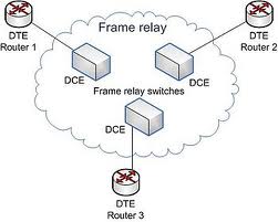
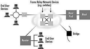
The fact that FRBS need not provide error detection/correction and flow control relies on the existence of intelligent end user devices, the use of controlling protocol layers, and high-speed and reliablecommunication systems. Access to the FRBS is via a frame relay interface defined between a date circuit-terminating equipment (DCE) on the network side and data terminal equipment (DTE) on the user side. While the Frame Relay standard specifies methods for setting up and maintaining both switched virtual circuits (SVCs) and permanent virtual circuits (PVCs), most implementations support only PVCs.
In 1990, four vendors – StrataCom, Digital Equipment Corporation, Cisco Systems and Northern Telecom – collaborated on developing a specification called the Frame Relay Specification with Extensions.
This document introduced a Local management Interface (LMI) to provide control procedures for permanent virtual circuits (PVCs). It is structured in to a basic mandatory part and a number of optional extensions.
The control procedures form three main functions:
- Link integrity verification initiated by the user device and continuously maintained.

- When requested by the user, full status network report providing details of all PVCs. Notification by the network of changes in individual PVC status, including the addition of a PVC and a change in PVC state (active/inactive).
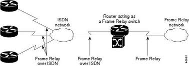
- ANSI and ITU-T define frame relay on ISDN. The Frame Relay forum has implementation agreements on various physical layers, including V.35 leased lines (56 kbps), T1, and G.704 (2.048 Mbps) . Generally, public carriers offer frame relay services from speeds of 56 kbps to T1/E1 speeds. Private networks may be implemented at higher and lower speed.
Question answers
Q1: Core functions used for frame relays?
Ans:
- Frame delimiting, alignment and transparency (using HDLC flags)
- Frame multiplexing and demultiplexing using the address field.
- Aligning frame boundaries
- Inspecting the frame to ensure that it is not too long or too short
- Detection of transmission errors using a frame check sequence (FCS)
- Congestion Control functions
Q2: What are the implications?
Ans:
- There is only 1 user type, used for carrying data.
- In-band signaling cannot be used.
- There are no sequence numbers, so no error control or flow control can be done.
Q3: What are The objectives for frame relay congestion control ?
Ans: Minimize frame discard.
- Maintain, with high probability and minimum variance, the agreed upon quality of service.
- Minimize the possibility of one end user’s monopolizing network resources at the expense of other end-users. (Fairness)
- Overhead on end-users should be limited.
- Limit the spread of congestion to other networks and other elements in the network
- Operate effectively regardless of traffic flow in either direction between end-users.
Q4: The constitute signals from the network to the end-user?
Ans : They are: Backward explicit congestion notification (BECN): This is set by the network when a frame traverses a congested virtual circuit in the opposite direction. A source that detects it is 1.transmitting on a congested path and is expected to reduce load. Forward explicit congestion notification (FECN): This allows the destination to discover that the path is congested and to notify the source transport to decrease its window and thus place less demand on the network. In OSI and DECnet Phase V environments, this bit can be mapped onto the congestion experienced bit in the header of the network layer PDU.
Q5: Three header formats are recognized what are these?
Ans: 1.Direct Network Layer Protocol Identifiers (NLPID) – protocols for which an NLPID value is
defined in ISO TR 9577: e.g., IP, CLNP (ISO 8473),
2.SNAP encapsulation – using SNAP NLPID followed by SNAP: LAN bridging, Connectionless
protocols which have a SNAP value (e.g., DECNET, IPX, AppleTalk etc.).
3. NLPID followed by four octets indicating layer 2 and layer 3 identifications: connection oriented
protocols (e.g., ISO 8208, SNA, etc.) and other protocols which can’t be supported by the other
methods
« ITC Interview Questions with Company Details wireless sensor networks »


Tell us Your Queries, Suggestions and Feedback