

Microwave source: Klystron
Last Updated: Jul 31, 2013
KLYSTRON
There are mainly two types of Klystrons:
- Two cavity klystron
- Reflex Klystron
TWO CAVITY KLYSTRON
Two cavity Klystron is a microwave vacuum tube using two cavity resonator to produce velocity modulation of electron beam and to produce amplification.
Construction

t is a 2-cavity kystron,also known as multicavity klystron.
Filament:Its function is to heat the cathode.
Cathode:Its function is to emit electrons(after heated by filament)
Focussing Anode:Its function is to pass the electrons into a narrow beam.
Bunching Cavity:
- It is the input cavity at which the electrons are bunched and passed towards right.
- Also microwave signal is given at the input path of this cavity
Catcher Cavity
- It is the output cavity at which the output is taken which is at the end side of the tube.
Plate(collector)
- It is connected to positive voltage side and its function is to collect the electrons.

Operation
The emitted electrons are passed to a narrow beam by focusing anode .This sharply focused beam of electrons is then forced to pass through 1st cavity resonator .The microwave signal is provided at the input side of the buncher cavity.
During the positive half cycle the focused electrons accelerate and in negative half cycle decelerate .This speeding and slowing process is called velocity modulation or bunching process and this process takes place at input cavity which is known as Buncher cavity .
This bunched electrons are attracted by positive plate because the plate is connected positive terminal of the voltage .So this attraction results in passing the electrons through the output path in 2nd cavity. So this cavity is called catcher cavity. But another RF field is maintained at catcher cavity. So these bunch electrons of RF signal increase. As more speeded bunch electrons interact they liberate energy and hence more amplification occurs at catcher cavity this further results in more amplified energy which is extracted from this cavity outlet and electrons after releasing energy attracted to positive plate and complete a path. So 2-cavity klystron is called an amplifier.
REFLEX KLYSTRON
Reflex Klystron is a single cavity variable frequency generator of low power and low efficiency .This is widely used in application where variable frequency is desired as:
- local oscillator in microwave receiver
- In radar receiver
- Pump oscillator in parametric amplifier
Construction

Reflex klystron consists of an electron gun, a filament surrounded by cathode and a focusing electrode at cathode potential .The electron gun emits the electrons with constant velocity given by
½ mVo²=qVa
Vo=√2qVa/m m/s (initial velocity of electrons)
- The magnetic field is applied to focus the electron in the centre of the tube.
Operation
- The electrons are emitted from cathode with a constant velocity enter the cavity where there velocity is changed depends upon the cavity voltage.
- Assuming that the oscillation is started by the device due to high quality factor or due to noise signal and to make it sustained we have to applied the feedback .Hence there are certain favorable electrons which will bunch together to deliver the energy at a time to the RF signal.
- Inside the cavity velocity modulation takes place. It is a process in which the velocity of the emitted electrons are modified or changed with respect to cavity voltage
V0’=√2q(Va+Vi sin wt)/m (exit velocity of electrons after cavity
- In the cavity gap the electron beams get velocity modulated and get bunched in the drift space existing between the cavity and the repeller.
- Bunching is a process by which the electrons take energy from the cavity at different time and delivered to the cavity at the same time as shown in fig
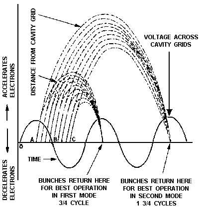
mode frequency characteristics
Transit time :The time spent by the electrons in the cavity space or the time taken by the electrons to leave the cavity and again return to the cavity.
let t¹ be the time at which electrons leave the cavity and t² is the time at which they bunch into the cavity ,then transit is given by
tr=t²-t¹
- During that the net displacement is zero
Vab =Va-Vb
=Va +Vi sin wt +Vr
= Va+ Vr(neglecting ac term )
then electric field E= -d Vab/dx
=-Vab/S
Force F=qE=-q(Va+Vr)/s (1)
we also know,F=ma=m.d²x/dt² (2)
comparing (1) and (2)
d²x/dt²=-(q/ms)(Va + Vr) (3)
integrating both sides to euation (3)
dx/dt=-q/mS(Va+Vr)(t-t¹)+v(t¹)
Again integrating from t to t¹ we get
x=-q/mS(Va+Vr)(t-t¹)²/2 + V(t¹)(t-t¹) +k2
where k2 is the displacement constant(being small so it is neglected)
At t=t², x=0
tr=t²-t¹=2mSV(t¹)/q(Va+Vr)
similarly transit angle can be given by
w(t²-t¹)=(2n∏-∏/2) =2mSwV(t¹)/q(V0+Vr)
Output power as a function of repeller voltage
The beam current of reflex klystron is given by
Ib=-Io-∑2IoJn(nX)cos( nwt-Φ) (from n=1 to ∞)
The fundamental component of current
If=-2Io J‚(X’)
I2=-Kf If =2Io Kf J‚(X’)
output power =ViI2/2
=2 Va Io J‚(X’) X’/( 2n∏-∏/2 )
output power is directly proportional to repeller voltage.
Question and answer
Q) A reflex klystron operates at the peak mode of n=2 with beam voltage Vo=300V beam current Io=20 mA ,signal voltage V1=40V.determine the input power in watts ,output power in watts and efficiency?
Ans) Input power=Vo Io =300*20/1000=6 watt
output power = 2Vo Io J‚(X’)X’ /( 2n∏-∏/2 )=2×6×1.25/(2×2∏-∏ ⁄ 2)=1.36 watt
efficiency (η)=output power/input power ×100 %=(1.36×100)/6 %=22.7%
Q)what is the function of the buncher and catcher cavity ?
Ans) Function of Bunching Cavity:
- It is the input cavity at which the electrons are bunched and passed towards right.
- Also microwave signal is given at the input path of this cavity
Function of Catcher Cavity
- It is the output cavity at which the output is taken which is at the end side of the tube.
Q) How reflex klystron differ from two cavity klystron?
Ans) In two cavity klystron there are two cavity i.e. Buncher cavity and Catcher Cavity.Buncher cavity is the input cavity at which the electrons are bunched and the catcher cavity is the output cavity at which the output is taken but in reflex Klystron only one cavity is present where the bunching process as well as output taken.
Q)What do you mean by Dominant mode in reflex klystron?
Ans) When bunching process occurs in reflex Klystron, it is seen that when the electrons returns to the cavity in the second positive peak i.e 1¾ cycle.We can obtain the maximum power, hence it is called Dominant mode.
GATE Syllabus-
1. Gate syllabus for Electronics and Communication Engineering
IES Syllabus-
1. IES Syllabus for Electronics and Telecomm
2. IES Syllabus for General Ability
Discover more from Our Education | Best Coaching Institutes Colleges Rank
Subscribe to get the latest posts sent to your email.
« Nagaland Board Sample Paper of English for Class 10 Sample Paper for AIEEE Exam »
Tell us Your Queries, Suggestions and Feedback