
ELECTRICAL MACHINE DESIGN PERMANENT MAGNET SYNCHRONOUS MOTOR
Last Updated: Jun 24, 2013
ELECTRICAL MACHINE DESIGN PERMANENT MAGNET SYNCHRONOUS MOTOR
PERMANENT MAGNET SYNCHRONOUS MOTOR:
A permanent magnet synchronous motor is also called as brushless permanent magnet sine wave motor. Permanent magnet synchronous machines generally have the same operating and performance characteristics as synchronous machines. A permanent magnet machine can have the configuration almost identical to that of the conventional synchronous machine with the absence of slip rings and a field winding.
CONSTRUCTION:
STATOR:
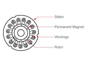
PERMANENT MAGNET SYNCHRONOUS MOTOR
Stator lamination’s for axial air gap machines are often formed by winding continuous strips of steel. Various parts of the lamination’s are the teeth slots which contains armature windings. Yoke completes the magnetic path. Lamination thickness depends upon the frequency of the armature source voltage and cost.
Armature windings are generally double layer and lap wound. Individual coils are connected together to form phasor groups. Phasor groups are connected in series/parallel combinations to form star, delta, two phase or single phase windings.
AC windings are generally short pitched to reduce harmonic voltage generated in the windings.
Coils, phase groups and phases must be insulated from each other in the end-turn regions and the required dielectric strength of the insulation will depend upon the voltage rating of the machine.
ROTOR:
There are generally four types of rotors in PMSMs. They are
- Peripheral rotor
- Interior rotor
- Claw pole or lundell rotor
- Transverse rotor

rotation process working
Permanent magnet forms the pole equivalent to the wound field poles of conventional synchronous machines. Permanent magnet poles are inherently “salient” and there is no equivalent to the cylindrical rotor pole configurations used in many conventional synchronous machines.
Many permanent magnet synchronous machines may be cylindrical or “smooth rotor” physically but electrically the permanent magnet is still equivalent to a salient pole structure. Some of the PMSM rotors have the permanent magnets directly facing the air gap.
Rotor yoke is the magnetic portion of the rotor to provide a return path for the permanent magnets and also to provide structural support. The yoke is often a part of the pole structure.
Damper winding is the typical cage arrangement of conducting bars, similar to induction motor rotor bars and to damper bars used on many other types of synchronous machines. It is not essential for all permanent magnet synchronous machine applications, but it is found in most machines used in power applications.
for more electrical machine design notes
- electrical machine design limitations
- electrical machine design question paper
- electrical machine design switched reluctance motor
- electrical machine design synchronous generator
GATE Syllabus-
1. Gate syllabus for Electrical Engineering 2014
2. Gate syllabus for Mechanical Engineering 2014
IES Syllabus-
1. IES Syllabus for Electrical Engineering
2. IES Syllabus for Mechanical Engineering
Discover more from Our Education | Best Coaching Institutes Colleges Rank
Subscribe to get the latest posts sent to your email.
This is the few important concepts in electrical engineering . Students belonging to this trade can clear their doubts regarding this topic.
Understanding the concept of permanent motor is one difficult task, but after gothroughing this article it’s becomes very easy with the pictorial representation . very nice and good article….
Permanent magnet synchronous motor are called as brushless motors. these motors are really effective at the place where there is required much speed …. these motors are specially placed in generators to produce more fluctutaion to generate more electricity……. very nice post good to get it learn