
Inverters
Last Updated: Aug 6, 2013
INVERTERS
PULSE WIDTH MODULATED (PWM) INVERTERS
Introduction
- Inverters are circuits responsible for converting DC to AC
- It helps in transferring power from a dc source to an ac load.
- The applications areas of inverters such as:
- Adjustable-speed ac motor drives
- Uninterrupted power supplies (UPS)
- Running appliances of ac used in an automobile battery.
- power transmission industry such as reactive power controllers and adaptive power filters
TYPES OF INVERTERS.
The classification of inverters are based on the following properties”
1. supply type
2. configuration of circuit.
3. control method.
The types of inverters based on supply are.
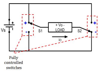
-> voltage sourced inverters: These days the topology commonly used for AC output appliances is the DC/AC voltage source inverter as shown in fig.1. The output voltage(AC) is produced with the help of a pulse width modulated waveform. The modulation components of the current are filtered by the low pass characteristic of typical inductive power electronic loads.

fig. 1 voltage sourced inverter
-> current sourced inverters

fig. 2 parallel diode to provide a return path for current
Single phase Bridge Inverter:
These are of two types:
Single phase Half Bridge Inverter:
These inverters consists of two switches s1 and s2 which divides the DC voltage source into two parts with the help of capacitors.
This inverter is also called as “INVERTER LEG”
It provides the flow of current even when the circuit is opened.
Amplitude & Harmonics Control
The fundamental frequency amplitude of square wave output from the full bridge inverter is calculated from it’s dc i/p voltage.
The switching scheme is modified for the production of a produced a controlled o/p
An o/p voltage has intervals if the output voltage is said to be zero , + Vdc and – Vdc.
The o/p voltage is controlled with the help of adjusting the interval on each side of the pulse where the output is zero.
Single Phase Inverter – PWM Control Strategy
There are various Criteria that needs to Considered for Controlling Single Phase Inverter
Those few criteria that we need to look at:
- range of O/p voltage
- Maximum output voltage
- Switching losses
- Distortion in o/p and i/p sides (which is measured according to the inverter performance)
Pulse Width Modulation (PWM)
- PWM provides methods that decreases the total harmonic distortion of the load current.
- THD requirements is met easily instead of the square wave switching scheme for PWM inverter.
- The unfiltered o/p of PWM carries a relatively high THD. But, due to the frequencies of harmonics it can be easily filtered.
Sinusoidal Pulse Width Modulation (SPWM)
The SPWM requires a reference- a modulating or control signal that is sinusoidal. And also a carrier signal that is a triangular wave which controls the switching if frequency.
Questions and answers.
Q1> What are the functions of switches?
Ans> The functions of switches is to carry current in both the directions for a pulse width modulation.
Q2> what is a reference voltage?
Ans> A sinusoidal reference voltage is generated within the control circuit of the inverters. The reference voltage may be sinusoidal or non sinusoidal.
GATE Syllabus-
1.Gate syllabus for Electronics and Communication engg
2.Gate syllabus for Electrical Engineering
IES Syllabus-
1. IES Syllabus for Electrical Engineering
2. IES Syllabus for Electronics and Telecomm
Discover more from Our Education | Best Coaching Institutes Colleges Rank
Subscribe to get the latest posts sent to your email.
« Wireless communication system and the technical challenges Top Arts colleges in Manipur »
Tell us Your Queries, Suggestions and Feedback