

Construction of DC Motor
Last Updated: Jul 31, 2013
CONSTRUCTIONAL ASPECTS OF DC MACHINE
The main objective is to highlight the constructional aspect of a DC machine in general while analysing the operating principles of a DC generator /DC motor in particular.
According to the construction ,there is no significant difference between a DC motor and a DC Generator.Hence ,the same machine can perform both the operations,which means a DC machine manufactured for the purpose of a DC generator can also be used as a DC motor and vice-versa.Hence ,the DC generator and DC motor are generally referred as DC machines.
The major parts can be identified as:
1. Body
2. Poles
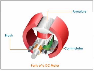
3. Armature
4. Commutator and brush gear
5. Commutating poles
6. Compensating winding
7. Other mechanical parts
The constructional aspects relating to these parts are now discussed briefly in sequence:-
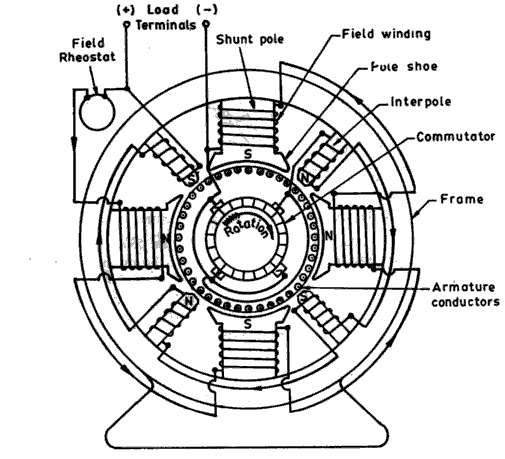
1.Body-The body constitutes the outer shell within which all the other parts are housed.This will be closed at both the ends by two end covers which also support the bearings required to facilitate the rotation of the rotor and the shaft. Even though for the generation of an emf in a conductor a relative movement between the field and the conductor would be enough, due to practical considerations of commutation, a rotating conductor configuration is selected for d.c. machines. Hence the shell or frame supports the poles and yoke of the magnetic system. In many cases the shell forms part of the magnetic circuit itself. Cast steel is used as a material for the frame and yoke as the flux does not vary in these parts. In large machines these are fabricated by suitably welding the different parts. Those are called as fabricated frames. Fabrication as against casting avoids expensive patterns. In small special machines these could be made of stack of lamination suitably fastened together to form a solid structure.
2.Main poles– Solid poles of fabricated steel with separate/integral pole shoes are fastened to the frame by means of bolts. Pole shoes are generally laminated. Sometimes pole body and pole shoe are formed from the same lamination. Stiffeners are used on both sides of the lamination. Riveted through bolts hold the assembly together. The pole shoes are shaped so as to have a slightly increased air gap at the tips.
Inter-poles-These are small additional poles located in between the main poles. These can be solid, or laminated just as the main poles. These are also fastened to the yoke by bolts. Sometimes the yoke may be slotted to receive these poles. The inter poles could be of tapered section or of uniform cross section. These are also called as commutating poles or compoles. The width of the tip of the compole can be about a rotor slot pitch.
3.Armature– The armature is where the moving conductors are located. The armature is constructed by stacking laminated sheets of silicon steel. Thickness of these lamination’s kept low to reduce eddy current losses. As the lamination’s carry alternating flux the choice of suitable material, insulation coating on the laminations, stacking it etc are to be done more carefully. The core is divided into packets to facilitate ventilation.The winding cannot be placed on the surface of the rotor due to the mechanical forces coming on the same. Open parallel sided equally spaced slots are normally punched inthe rotor laminations. These slots house the armature winding. Large sized machines employ a spider on which the laminations are stacked in segments. End plates are suitably shaped so as to serve as ’Winding supporters’. Armature construction process must ensure provision of sufficient axial and radial ducts to facilitate easy removal of heat from the armature winding
4.Field windings- In the case of wound field machines (as against permanent magnet excited machines) the field winding takes the form of a concentric coil wound around the main poles. These carry the excitation current and produce the main field in the machine.Thus the poles are created electromagnetically. Two types of windings are generally employed. In shunt winding large number of turns of small section copper conductor is used. The resistance of such winding would be an order of magnitude larger than the armature winding resistance. In the case of series winding a few turns of heavy cross section conductor is used. The resistance of such windings is low and is comparable to armature resistance. Some machines may have both the windings on the poles.The total ampere turns required to establish the necessary flux under the poles is calculated from the magnetic circuit calculations. The total mmf required is divided equally between north and south poles as the poles are produced in pairs. The mmf required to be shared between shunt and series windings are apportioned as per the design requirements. As these work on the same magnetic system they are in the form of concentric coils. Mmf ’per pole’ is normally used in these calculations.
5.Armature winding -As mentioned earlier, if the armature coils are wound on the surface ofthe armature, such construction becomes mechanically weak. The conductors may fly away when the armature starts rotating. Hence the armature windings are in general pre-formed, taped and lowered into the open slots on the armature. In the case of small machines, they can be hand wound. The coils are prevented from flying out due to the centrifugal forces by means of bands of steel wire on the surface of the rotor in small groves cut into it. In the case of large machines slot wedges are additionally used to restrain the coils from flying away. The end portion of the windings are taped at the free end and bound to the winding carrier ring of the armature at the commutator end. The armature must be dynamically balanced to reduce the centrifugal forces at the operating speeds.
6.Compensating winding– One may find a bar winding housed in the slots on the pole shoes. his is mostly found in d.c. machines of very large rating. Such winding is called compensating winding.
7.Commutator- Commutator is the key element which made the d.c. machine of the present day possible. It consists of copper segments tightly fastened together with mica/micanite insulating separators on an insulated base. The whole commutator forms a rigid and solid assembly of insulated copper strips and can rotate at high speeds. Each commutator segment is provided with a ’riser’ where the ends of the armature coils get connected. The surface of the commutator is machined and surface is made concentric with the shaft and the current collecting brushes rest on the same. Under-cutting the mica insulators that are between these commutator segments has to be done periodically to avoid fouling of the surface of the commutator by mica when the commutator gets worn out..
8.Brush and brush holders– Brushes rest on the surface of the commutator. Normally electro-graphite is used as brush material. The actual composition of the brush depends on the peripheral speed of the commutator and the working voltage. The hardness of the graphite brush is selected to be lower than that of the commutator. When the brush wears out the graphite works as a solid lubricant reducing frictional coefficient.More number of relatively smaller width brushes are preferred in place of large broad brushes. The brush holders provide slots for the brushes to be placed. TBrush holder with a Brush and Positioning of the brush on the commutator from the brush is taken out by means of flexible pigtail. The brushes are kept pressed on the commutator with the help of springs. This is to ensure proper contact between the brushes and the commutator even under high speeds of operation. Jumping of brushes must be avoided to ensure arc free current collection.
9.Other mechanical parts- End covers, fan and shaft bearings form other important mechanical parts. End covers are completely solid or have opening for ventilation. They support the bearings which are on the shaft. Proper machining is to be ensured for easy assembly. Fans can be external or internal. In most machines the fan is on the non-commutator end sucking the air from the commutator end and throwing the same out. Adequate quantity of hot air removal has to be ensured.
10.Bearings- Small machines employ ball bearings at both ends. For larger machines roller bearings are used especially at the driving end. The bearings are mounted press-fit on the shaft. They are housed inside the end shield in such a manner that it is not necessary to remove the bearings from the shaft for dismantling. The bearings must be kept in closed housing with suitable lubricant keeping dust and other foreign materials away. Thrust bearings, roller bearings, pedestal bearings etc are used under special cases. Care must be taken to see that there are no bearing currents or axial forces on the shaft both of which destroy the bearings.
QUESTION & ANSWER
Q1.What are the different parts of DC Machines?
Ans:Body(Stator) ,Poles, Armature(rotor), Commutator and brush gear, Commutating poles, Compensating winding.
Q2.Is there any constructional difference between DC motor & DC genarator?
Ans:There is no constructional difference between them.There exist only the operational difference that DC generator takes mechanical energy as input & gives electrical energy as output and DC motor takes electrical energy as input & gives mechanical energy as output .
Q3.What is the function of the commutator and brushes?
Ans :The function of the commutaor is to rectify the AC emf into DC emf voltage and then,filter out the ropples present in the DC voltaged and tries to make it smooth..Thus ,commutator is often termed as a mechanical rectifier.
The function of the brushes is to collect the AC current.
Q4.The armature is constructed by stacking laminated sheets of silicon steel.Explain why?
Ans:The armature is constructed by stacking laminated sheets of silicon steel. Thickness of these laminations kept low to reduce eddy current losses.
Q5 what is the function of Yoke?
Ans:A DC machine has a stationary cylindrical frame called yoke,which supports the magnetic field system in the form of projected north and south poles.
Discover more from Our Education | Best Coaching Institutes Colleges Rank
Subscribe to get the latest posts sent to your email.
Tell us Your Queries, Suggestions and Feedback
19 Responses to Construction of DC Motor
« Boiler Trouble causes(water and its industrial application) Introduction to CE transistor configurations »
Electrical and electronics engineering
no
Construction if DC motor
NVTI. CERTIFICATE TWO
NVTI. CERTIFICATE TWO
NVTI. CERTIFICATE TWO
NVTI. CERTIFICATE TWO
project information related to “Image Processing based Fruit Sorting system(color,shape,size,weight)”
short notes & easily understandable points about dc motor & dc generator
in dc motor the stator have permanent magnet or electromangnet and same for rotor winding
It describes the total constructional features of dc machine i.e motor or generator . Also well labeled diagram is given for easy and better understand… go for it
The picture clarity and position where it is placed was absolutely superb,
all the best
The constructional aspects of the DC motor/generator can be easily understood by the above article…It has been presented in a very appropriate way as one can easily understand bit by bit of it…just by going through 🙂