
Control System Engineering
Last Updated: Aug 2, 2013
Control System Engineering is the Part controlling devices used to control any processes processing in any device.The aim of the Systems and Control Engineering program is to provide recognized excellence for graduate and undergraduate education.
In this post the concept of Control System Engineering described in details weather how will control any machines and devices whenever they are at working moment.
Questions and Answer on Control Systems Engineering

Control Systems Engineering
1.(a) what is the difference between open loop and closed loop control system?
Ans– in open loop there is no feedback, it is easy to maintain, it is cheaper,in this case delay time is less and there is some disadvantage it is not accurate, eg-traffic signal, blind person, automatic washing machine,bread toaster, but in closed loop control control system there is a feedback, accurate in output, time delay is more, difficult to maintain. eg- automatic electric iron, human body ,economic imflation.
(b) what are the mathematical modelling of electrical elements?
Ans Capacitor- it store energy in electrical form. There is a relationship between the charge on a capacitor and the voltage across the capacitor. The relationship is simple. For most dielectric/insulating materials, charge and voltage are linearly related.
 Q = C V
-resistors,capacitors and inductors are the fundamental passive elements in electrical system
There is a relationship between the charge on a capacitor and the voltage across the capacitor. The relationship is simple. For most dielectric/insulating materials, charge and voltage are linearly related. Q = C Vinductor- It store the enrergy in magnetic field
Stored energy
The energy (measured in joules, in SI) stored by an inductor is equal to the amount of work required to establish the current flowing through the inductor, and therefore the magnetic field. This is given by:
where L is inductance and i the current Resistance- it is an energy dissipative element, the relation between voltage and current is v(t)= R i(t)
(c) what is signal flow graph,what are the advantage of signal flow graph?and how it is related to block diagram reduction technique?
Ans- Sfg is a technique which is used to represent output/input or it consists of a network graph in which nodes represent the system varibles nodes which are connected by directed branch .sfg is a easy technique to find out input by output relationship in this case there is a minimum step but in block diagram reduction technique there is more steps to find out i/p by o/p relation.Here in place of block there is node ,branch ,loop ,etc
(d)what are the effects of integral control action?
Ans- Integral control action improves the (1)Steady state response (2)Damping factor (3)Bandwidth Integral control action reduces (1)peak overshoot (2)Noise
(e)Illustrate Difference Between Root locus and Root counters?
Ans- The root locus is defined as the locus of the roots of the characteristic equation in the s-plane as the open loop gain ‘K’ is varied from 0 to∞. whereas Root counter is the locus of the Roots of the characteristics equation when more than one is varied in the system.
(f)Explain the physical significance of poles and zeros of a linear time invariant system? Ans-The stability of a system depends upon the location of the poles. if all the poles are located in left half of s- plane then the system is stable. If any pole is located In the Right half of s-plane , Then the system is unstable.Similarly a “Zero” in the system contribute the early peak to the system’s response i.e peak overshoot may increase appreciably.
(g)What is Nichol’s chart ?What Is It Advantage?
Ans-The Scientist Nichol’s transformed the constant-M and constant N-circles to log-magnitude and phase angle coordinates and the resultant chart is called Nichol’s Chart . Its advantage is;it gives both gain and phase of the closed loop system.
(h)What is necessity of tachometer in the negative feedback control system? explain. Ans-Tachometer is a small motor that develops an output voltage proportional to its shaft speed .Tachometer feedback is generally used to improve the performance of servo systems.The tachometer can be used for position control,velocity control & Speed read out . the advantage of using tachometer in -ve feedback control system is that it is easy to design and inexpensive.
(i)For stable linear whether Gain margin(GM) is positive or negative? justify your answer? Ans-Positive;The gain in db at phase cross -over frequency is the gain margin . if gain is negative , the gain margin is positive .then only the system will be stable . this is clear from nyquist criterion that, for the stable system ,the value of gain k is smaller than the value of critical point(-1+ j0) (j)State and explain the principle of PID controllers.
Ans-PID controller is the combination of proportional,integral& derivative control actions By combining all the three control actions ,the optimum performance can be achieved. the proportional controller (kp) will reduce the rise time& but will not eliminate steady state error. rather it will reduce it . an integral control (ki) will eliminate the steady state error,but it will make the transient response worse.A derivative control (kd) will increase the stability of the system by reducing overshoot & improving the transient response.
2. (a) Discuss the merits and demerits of block diagram representation of physical system compared to signal flow graph representation.
Ans-The input-output behaviour of a linear system or element of a linear system is given by transfer function G(S)=C(s)/R(s). the conveniont graphical representation of this behaviour is the block diagram algebra.but the demerits of block diagram is as follows, (1).It is time consuming process. (2) there is no specific rules which states,the next step during the execution of block diagram reduction technique. (3)It does not provide any physical insight pf the system parameter variation with respect to time can not be determined.so to over come this problem ,signal flow graph is used.
(b).In the formation of Routh’s array if all the elements in any one row of the routh array are zero, how do you proceed to apply the Routh’s stability criterion? explain,
Ans- steps(1)- If the complete row in the Routh’s array is zero,hence write the eqn of the row which is Above the zero row and it is known as Auxilliary eqn. STEP(2)- Differentiate it with respect to “s”. Step(3)-Replace the coefficients of this equation instead of zero row & complete the Routh’s array. To understand this,consider The example given below. example;Predict the stability of the system given by characteristics equation S5 +3S4+3S3+9S2+5S+15=0, now forming routh’s array as given below
S5 1 3 5
S 4 3 9 15
S3 0 0
Now, writing the Auxiliary equation for S4 ,
Row, we have
A(S)=3S4+9S2+15 ,Differentiating A(S) with respect to ‘s’
DA(S)=12S3+18S, now completing Routh’s array we have ,
S5 1 3 5
S4 3 9 15
S3 12 18
S 2 54/12 15
S1 -220
S0 15 so system is unstable.
(3)Explain the principle of operation and characteristics of a two phase servo motor.
Ans- Principle of operation of A.C servo motor :-
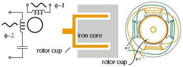
A.C servomotor are also called two phase induction motor. These motors have two parts . Namely stator and rotor. the stator has two windings,which are displaced from each other by 900 .
One winding is called main winding or reference winding and the winding is called control winding.The main winding is excited by a constant a.c voltage,where as the control winding is excited by a variable control voltage of same frequency as the main winding , but having a phase difference of 900 .
The variable voltage control for control winding is obtained from a Servo amplifier. The direction of rotation of the rotor depends upon the phase relationship of voltage applied to the two windings.It can be reversed by reversing the phase difference between control voltage and main voltage.gap
The rotor of a.c servomotors are of two types.
(a)Squirrel cage rotor
(b)Drag cup type rotor.
The squirrel cage rotor has large length and small Diameter. so its resistance is very high. the air gap of squirrel cage is kept small.In drag type cup rotor has two air gaps.for this air gap a cup of two non magnetic material is used .A stationary iron core is placed between the conducting cup of complete the magnetic circuit.So the resistance of drag type cup is high and therefore has high starting torque.
Characteristic of 2-phase a.c servomotor:
Torque-Speed characteristics :
It depend upon the ratio of reactance to resistance .
(4)Can you determine Gain margin(GM)&Phase margin(PM) from the Nyquist plot ?
Ans- Determination of gain margin(GM) :
Gain margin is a factor by which the system gain can be increased to drive the system into the verge of instability. It is calculated at phase cross over frequency. phase cross over frequency is the frequency at which the phase or angle of open loop transfer function is 1800
<G(S)H(S) at w=wp=1800
|G(jw)H(jw)|at w=wp=a
Gain margin =(1/a)
Gain margin in DB=20 log(1/a) = -20 log a dB
Determination of phase Margin(PM) :
phase margin is the additional phase given to the system to drive the system into the verge of instability. it is calculated as frequency called Gain cross over frequency.Gain cross over frequency at which system gain attains the value 1.
i.e-
|G(jw)H(jw)|at w=wg=1
<G(jw)H(jw) at w=wg=θ
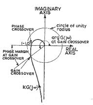
Phase margin
(Φm)=θ+1800
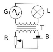
(5) Describe the construction , working and applications of an Amplidyne.
Ans- Amplidyne (Rotating Amplifier)
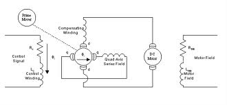
In control system ,Rotating amplifier or amplidyne is a machine that produces
large power amplification. it is similar to D.C generator which produces two stage amplification.
Construction – The construction of Amplidyne is shown above.
It is generally a two pole machine having two field windings which are placed with 900.
The controlled field windings is used to produced a flux (Φd) is direct axis . the field winding at (900) to it is called quadrature axis, consisting of quadrature winding.The armature is driven by a prime mover.
Working principle-
Under steady d.c condition, control fixed voltage causes a constant field current to flow, produces a flux (Φd)in direct axis. this flux induces a voltage
(eq) across the brushes ‘qq‘ and a current (iq)is establish in the quadrature axis .the function of compensation winding is to prevent the armature reaction
flux produced by the output current (Id) from reducing the original field ‘Φd’ .
Applications–
1.It can be used to control various quantities like current ,voltage and speed.
2.for power factor control of synchronous motor ,generator set.
3. for a.c voltage regulation in big generators.
3. for speed control units in paper mills.
(6)Write short notes on any two of the following :
(a)sensors (b)magnetic amplifier
Ans- (a) sensors:
These are low power transducers which produces output signal as a measure of the controlled variables. sensors are employed for variety of measurements. such as position ,velocity,acceleration ,pressure ,temperature
or a quantity representing the chemical state of the reactor ,neutron flux in an atomic reactor etc. the output of the sensor is in electrical form.
(b) Magnetic amplifiers: the electromagnetic device for amplifying electrical signals. it an alternative to vacuume tube amplifier where robustness & high current capacity were required.
Principle of operation :
Generally a magnetic amplifier is a saturable reactor . it makes use of magnetic saturation of the core . for controlled saturation characteristics , the magnetic amplifier employs core materials that have been designed to a specific B-H curve that is highly rectangular, in contrast to slowly tapering B-H curve of softly saturating core materials that are often used in normal transformers. it consists of two physically separate but similiar transformer magnetic core .Each is having two windings.A control winding and an A.C winding A low D.C current from a low impedance source is fed into the series connected control windings.The A.C winding is connected either in series or in parallel . The amount of control current fed into the control winding sets The point in A.C winding waveform at which core will saturate.In saturation the A.C winding on the saturated core will go from a high impedance state (ON). That is control current controls at which voltage of magnetic amplifier switches (ON).
7.) What is root locus and what are the steps for drawing root locus? [10]
Ans-Root locus is defined as the locus of roots of characteristics equation in the S-plane.
As the open loop gain is varied from 0 to . The locus of roots of characteristics equation in the S-plane as k varies from – is called inverse root locus. The complete root locus is combination of root locus and inverse locus.
Steps for Drawing Root Locus :
(1) The root locus starts from open loop poles where the value of ‘k=0’ and ends at where the value of k = . If the open T.F. has finite zeros the no. of root loci ending at =(p-z).Where p is equal to no. of poles and z is equal to no.of zeros.
(2)The no.of asymptopes =(p-z).The angle of asymptote φA=180(2q+1)/p-z were,q=0,1,2…….
Centroids of asymptotes
σA=[Σ(Real part of poles) – Σ(Real part of zeros)]/(p – z)
(3)Root locus is always symmetrical to real axis.
(4)Imaginary intersection of root loci is got from Routh array.
(5)The location of break away point is determined using equation dk/ds = 0.
(6) If complex poles are present angle of departure is calculated using relation φd=±(180+φ).
Where φ=net angle contribution at the pole by remaining poles and zeros.
=Σ(angle contributed by zeros)-Σ(angle contributed by poles)
(7) If complex zeros are present in transfer function, angle of arrival is calculated using relation
φA=±(180-φ).
Where φ is the net angle contributed at the zeros by the remaining poles and zeros.
=Σ(angle contributed by zeros)-Σ(angle contributed by poles)
(8) The value of k on root locus is given by=(product of phaser length of poles/product of phaser length
Of zeros)
(9) that segment of s-plane contains root locus if the number of poles and zeros to the right of the segment is odd.
Discover more from Our Education | Best Coaching Institutes Colleges Rank
Subscribe to get the latest posts sent to your email.
Tell us Your Queries, Suggestions and Feedback
4 Responses to Control System Engineering
« Placement Criteria for Madhucon projects ltd ICSE ENGLISH SAMPLE PAPER CLASS 8 »
all questions regarding control engineering is really very good and knowledgeful. Thank you for these questions .can you please give more questions on control engineering. If you post more questions then i am really thankful of you…………
This article contains good information about control system engineering. it is helpful to understand. and format of article is good.
Control system engineering is a very important concept. This article is very useful to learn about it.
The use of subscript and superscript in this article is very good
the format of the picture and the alignment of the picture is very good, all the best way to go