
Radar Receiver
Last Updated: Jul 31, 2013
RADAR RECEIVER: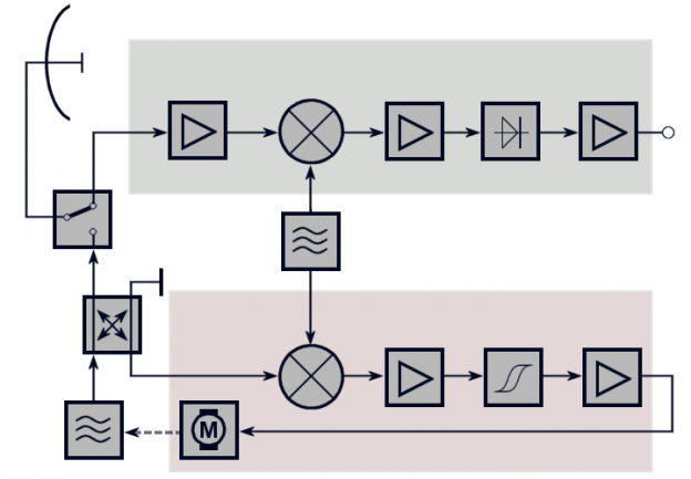
ANTENNA RECEIVER :
The radar antenna receiver system helps in detecting the emissions from the radio of radar systems . The radar receivers help in amplifying the signals received preventing it from noise and any type of distortion . It also optimizes the detection probability by increasing its bandwidth characteristics and provides a vast range to keep cluster signals . The antenna receiver helps in optical detection by deletion of large interfering signals . Radar signals require :
- The minimum detectable signal ( MDS )
- Bandwidth
- Dynamic range
1.The minimum detectable signal ( MDS ) : Minimum receivable power is important because this is one of the factor or characteristics which describes the maximum range performance of the radar . Based on certain requirements the radars are designed to have a sensitivity level . A radar having greater sensitivity than required will limit the bandwidth and will start processing the signals it has no interest with . The higher the power level given at the time of processing , fewer number of false alarms are processed and hence the detection of good noise signal will reduce .
2. Bandwidth : Receiver noise is the most important factor of radar receiver . The antenna receiver adds some noise to signal , very similar to that of other receivers because noise due to thermal action is unavoidable . Hence the receiver bandwith is directly proportional to certain amount of thermal noise . Hence the reduction of bandwith acts as a proper solution to the problem of receiver noise
3. Dynamic range : The signal received must be amplified without distortion . If a large number of signals is send to saturation level , then a modification to the spectrum signal is the solution . The MTI improvement factor degrades because of this reduction of spectral content . Delay will also take place in target detection restoration if the receiver enters saturation level .
The transmitters and the radar receivers are not always in the same location . The receiving antenna that captures the radar signals are weak and can be made stronger by using amplifiers .
NOISE FIGURE :
A noise factor converted to decibel is called Noise figure ( NF) . The measure of defall of any signal to noise ratio components in radio frequency signal chain for a bandwidth given is Noise figure . Hence the noise power also increases from input to output . It is also defined as the amount of reduction that occurs in the noise ratio . It can be both expressed by ratio or in decibels. .
MIXTURES :
This stage helps in increasing the received frequency to any intermediate frequency . The input from local oscillator is also received by mixer . The input is obtained by heterodyning by beating the two signals together . The second frequency reception’s result is a mirror image around the intermediate frequency . This can be represented by :
- fIF = frx – flocal oscillator
- fIF = flocal oscillator –frx
DISPLAYS – TYPE A :
The type A cannot show the direction but can only show the range . it can be also called as R scope . It is an electroscopic oscilloscope which was used in World War 2 . it could produce an oscillating voltage signal from the receiver of radar . It represents any signal detected on vertical axis . It has its application in aircrafts and ships . An A scope display was also used in air surface vessel radars and it used two antennas with a common reflector in front . The main disadvantage is that it was unable to indicate the direction to target .
LONG WIRE ANTENNA :
Long wire antennas are simple antennas . They are mostly efficient like upto a half wave antenna . They are made longer and so are installed almost close to the ground . The main advantages are they are very simple and inexpensive . The main disadvantages are they are a single wire feeder and are dangerous at the time of lightning .
LOW NOISE RECEIVER FRONT END :
A single chip low noise receiver front end includes low noise amplifier and a mixer and is applied at 77 GHz in automotive radars . This uses a SiGe HBT Technology to be implemented . A minimum measured single side band noise figure is represented by the front end of 11.5 dB . The main advantage is that this can be linearly measured .
SYNTHETIC APERTURE RADAR AND CONTINUOUS APERTURE SOURCES :
The main characteristics of aperture radar is relative motion between the target region and antenna to provide long term signal variations that are supposed to be generated from spatial resolution . It is mostly used in a platform that is moving by mounting on it for example like aircraft or spacecraft and from here a target scene is illuminated again and again with radiowave pulses . It has been basically designed to collect more information . This uses the principle of combining many pulses to form a synthetic aperture but also includes some additional processing .
It’s images has many applications in sensing and mapping of both earth and other planet surfaces .
HF OVER THE HORIZON RADAR :
An ionospheric reflection is the most common type of OTH radar . Under some conditions the radio signals sent towards the ionosphere reflects back to the earth . and after reflection a small amount of this signal reflects back to the sky . hence the HF or high frequency behavior is exhibited by only a single range of frequency . Under these conditions the frequency range of these radio signals reflects back to the ground . and because the reflected back signal will be large than the signal that is reflected from target , these will require to differentiate background noise from the targets . Hence Doppler effect is used where frequency shift takes place by moving objects so that their velocity can be measured .This in a way defines OTH or over the horizon as the capability to detect the targets at large ranges like thousands of kilometers .
BISTATIC RADARS :
These type of radars consists of a transmitter and receiver separated by a distance that can be compared by the distance of the target . A monostatic radar is a radar in which both the transmitter and receiver are combined . There are specific classes of bistatic radars like :
Psedo-monostatic radars , forward scatter radars , multistatic radar , passive radar . The advantage of bistatic radars are :
- it has low maintenance cost
- It can operate without any clearance in frequency
- I converts the receiver operations
- I has light receivers and powerful and heavy transmitters .
- Due to geometrical effect the cross section of the radar is enhanced .
The disadvantages of this type of radar includes :
- The complexity of the systems
- The costs involved in giving communication between different sites
- There is no control over the transmitter
- It is very hard to deploy
ASR :
It stands for airport surveillance radar and is used in airports for displaying and detecting the exact position of aircrafts .It uses an automated radar terminal system to display data . This system was developed to control air traffic , separation of aircrafts , and provide weather advices .
QUESTIONS AND ANSWERS :
QUE > DEFINE ASR ?
ANS > It stands for airport surveillance radar and it is used in airports to display and detect the exact position of aircrafts in various regions . It uses an automated radar terminal system that enables the display of data . The applications are control air traffic , separation of aircrafts , and provide weather advices .
QUE > WHAT ARE THE ADVANTAGES OF BISTATIC RADARS ?
ANS> the advantages of bistatic radars are :
- the maintenance cost is low
- will be able to operate without any clearance in frequency
- It converts the operations of receivers
- It has light weight receivers and powerful and heavy transmitters .
- Due to geometrical effect the cross section of the radar is enhanced .
QUE > WHAT IS DISPLAY TYPE A RADAR ?
ANS > The type A does not show the direction but can only show the range . It can be also called as R scope radar . It was used in World War 2 as it also works as an electronic oscilloscope . It could produce an oscillating voltage signal from the receiver of radar . It represents any signal detected on vertical axis . It is used in aircrafts and ships . An A scope display was also used in air surface vessel radars and it used two antennas with a common reflector in front . The main disadvantage is that it was unable to indicate the direction to target.
IES SYLLABUS:
IES Syllabus for Electronics and Telecommunication
GATE SYLLABUS:
GATE Syllabus for Electronics and Communication
Discover more from Our Education | Best Coaching Institutes Colleges Rank
Subscribe to get the latest posts sent to your email.
« Sample Paper of Chemistry for AMRITA Entrance Exam Equalizer »
Tell us Your Queries, Suggestions and Feedback